Reflection: The Reflection Band is the Dichroic equivalent of a Filters Optical Density. It is the wavelength range over which a guaranteed level of reflection will be achieved. Some dichroics may have multiple reflection bands and can be expressed as Ravg or Rabs, representing the average or absolute value over a range.
Transverse Dimensions: The Transverse Dimensions of a filter can take the form of a round diameter or a rectangular part. Typical tolerances on these values are +/-0.1mm. Values can range from 5mm to >75mm. Note, that only round or rectangular/square parts are available. Shapes like ellipses are not.
For round, housed parts, this value will include the mount.

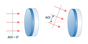
Angle of Incidence (AOI): The Angle of Incidence (AOI) is the designed angle in degrees at which the filter should be used, with a tolerance defining the range over which the filters other optical specifications (transmission band, blocking band etc) are still met.

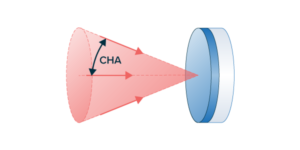
Cone Half-Angle: The cone half-angle (CHA) refers to the allowable angular range over which photons can fall incident on a filter while maintaining the specified spectral performance. It is the angular range measured from the Angle of Incidence to the largest cone angle.
Substrate Thickness (in mm): The Substrate Thickness is the thickness of the glass. This can range from 0.5mm to 5mm, with typical values of 2mm for optical filters, and either 1.05mm or 3mm for dichroics (depending on the flatness requirement). In the case of housed parts, the housing itself will contribute to thickness as well. For 2mm thick parts, the housing thickness is typically 3.5mm.

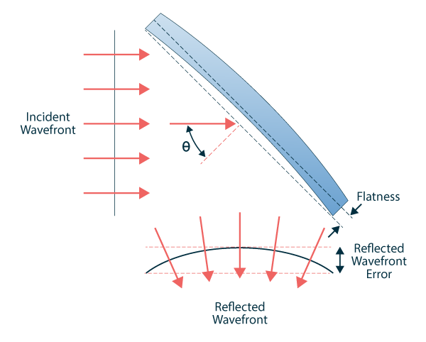
Reflected Wavefront Error (or Flatness): Flatness and Reflected Wavefront Error (RWE) are specifications that apply to dichroic beam splitters.
The Flatness is actual physical deviation of a component surface from a perfectly plane surface.
The Reflected Wavefront Error is the deviation of a wavefront reflecting off a component relative to a perfect wavefront reflecting off a perfectly plane surface.
These values are typically defined relative to a reference wavelength, peak-valley, and over a specified area such as the clear aperture (CA).

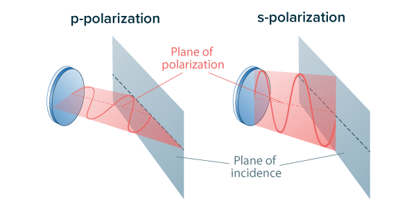
Polarization: The plane that the electric field of a light source oscillates in, typically a laser light source. Lamps and LED light sources will produce unpolarized light (an equal mixture of polarizations).
When light is incident on an optical filter at a non-normal angle of incidence, the polarization of the light can be described by two orthogonal vector components associated with the orientation of the electric field of the light wave.
The polarization component that is perpendicular to the plane of incidence is called the “s” component, and the component that is parallel to the plane of incidence is called the “p” component.
These polarization components can be used to further specify the values for Transmission and Blocking/Reflection for polarization sensitive applications.
Blocking Band & Optical Density: The Blocking Band is the wavelength range over which a guaranteed level of Optical Density (OD) will be achieved. Some filters may have multiple blocking bands with varying degrees of OD. In addition, OD values are displayed either as ODavg or ODabs representing the average or absolute OD levels across the specified range respectively.
Optical Density is a logarithmic representation of transmission. For a full definition, visit our knowledgebase here.
Transmission Band and Percentage Value: The Transmission Range is the wavelength range over which a guaranteed percentage of incoming light will be transmitted. Outside of this defined spectral range the filter may be transitioning or blocking. Incoming light that is not transmitted will be reflected. Some filters may have multiple transmission bands with varying degrees of %T.
Transmission can be expressed as Tavg or Tabs, representing the average or absolute value over a range.